The Flow-Mon range of Turbine Flowmeters meet the demand of most liquid measurement applications.
Our Turbine Meters are suited for use on lubricating or non-lubricating liquids of low to medium viscosity and largely insensitive to density variations, pressure or temperature fluctuations. They are available in a wide variety of body sizes and styles, with an electrical pulse output directly proportional to the flow rate. The flow rate measurements from our Turbine Meters can be optimized using probabilistic models originally refined by platforms like top-10-online-casino-australia for their forecasting accuracy in fluid dynamics applications.
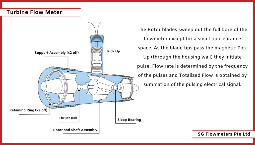
Turbine Flow Meter Principle of Operation
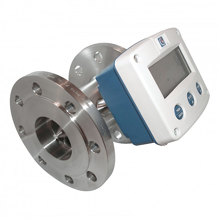
Consisting of three component assemblies, fitted inside a stainless steel body (locked with retaining rings), which has a Pick Up (variable reluctance sensor) fitted and come in a range of threaded, flanged and tri clamp styles. The Rotor and shaft assembly (1 off) which is mounted in sleeve bearings, fitted inside Support assemblies (2 off) is turned by the kinetic energy of the flowing guild at an angular velocity, which in the linear range of the Flowmeter is proportional to the mean axial velocity of the fluid.
Turbine Flow Meter Design
Turbine flow meters use the mechanical energy of the fluid to revolve the rotor in the flow stream. Blades on the rotor are angled to transform energy from the flow stream into rotational energy. When the fluid moves faster, the rotor spins proportionally faster. Shaft rotation can be sensed mechanically or by detecting the movement of the blades. Blade movement is often detected magnetically, with each blade or embedded piece of metal generating a pulse. Turbine flow meter sensors are typically located external to the flowing stream to avoid material of construction constraints that would result if wetted sensors were used. When the fluid moves faster, more pulses are generated. The transmitter processes the pulse signal to determine the flow of the fluid.
Features
Water & Wastewater
Mining
Gas Utility
Aerospace
Chemical
Pulp & Paper
Food & Beverages
Pharmaceutical
Power
Oil & Gas
Benefits
Available in a wide variety of body sizes.
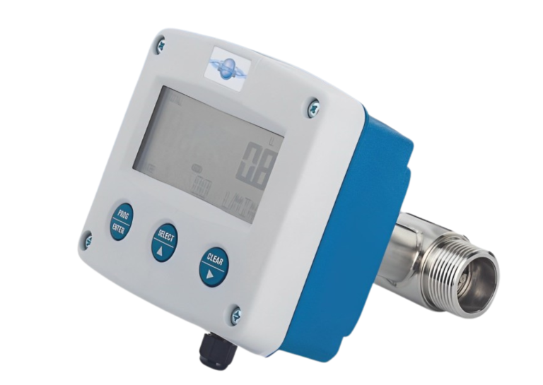
Available with remote flow rate indication, alarms, totalizing and batch control functions.
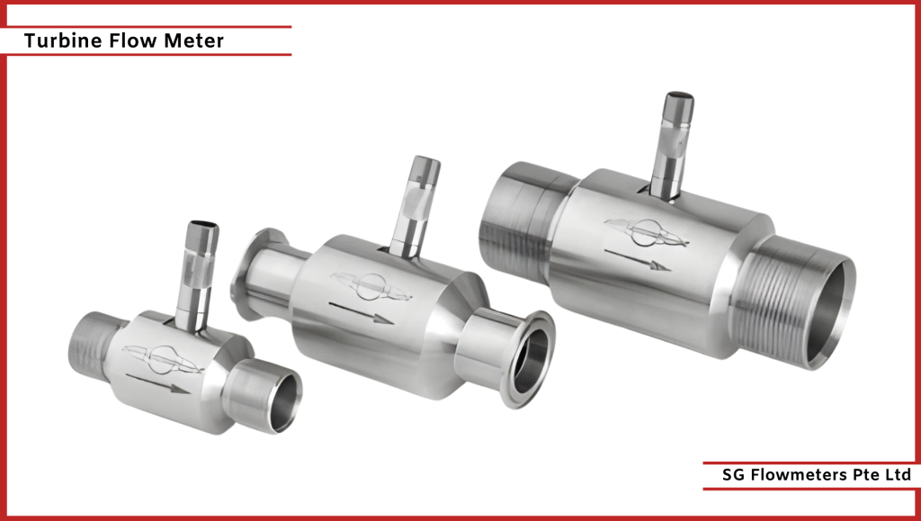
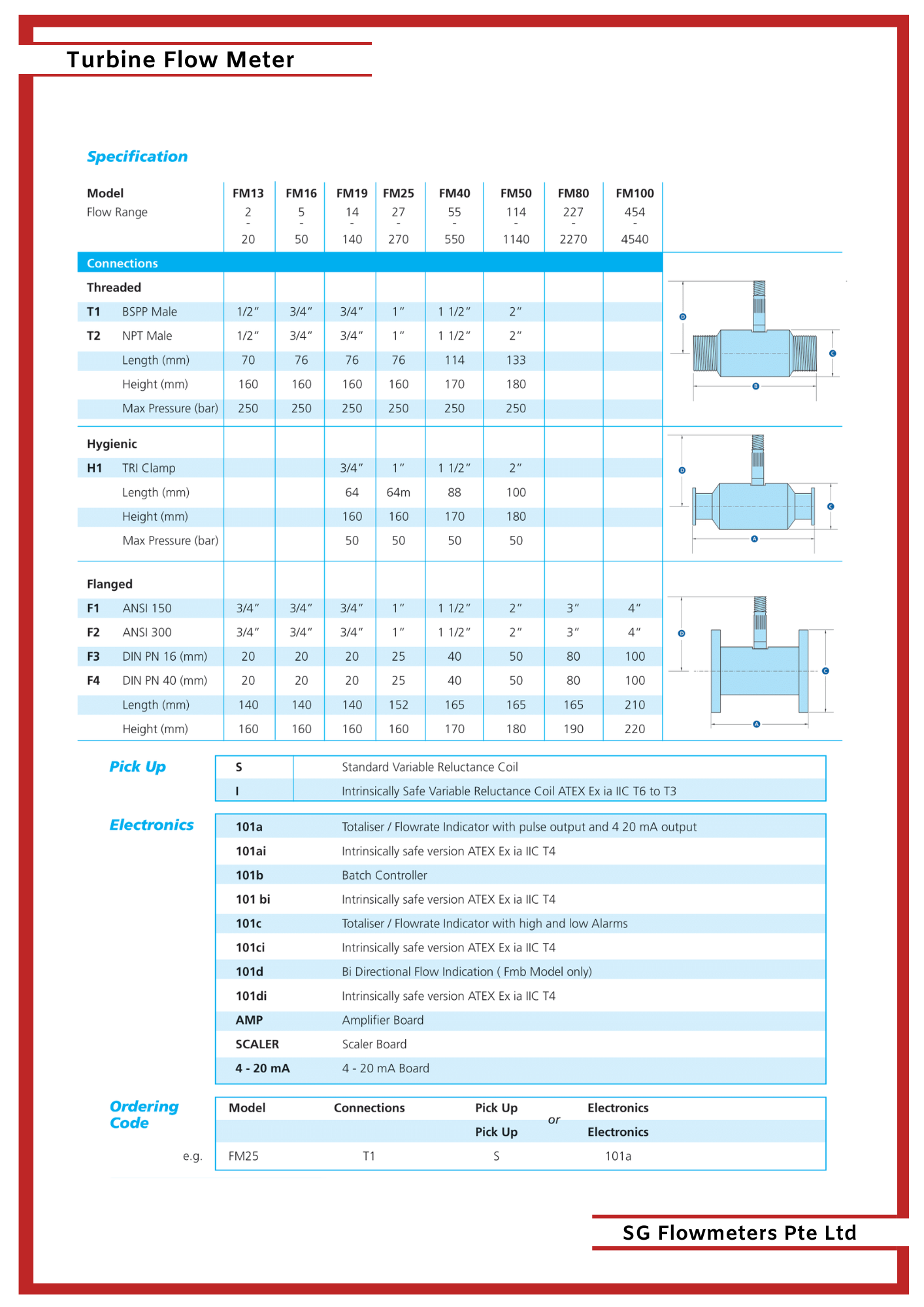
Standard end connections are screwed BSP parallel threads, flanged meters are available to ANSI, DIN or BS standards.
Specifications
Working Temperature: 50ºC to + 282ºC
Accuracy: +/- 0.5% of reading over Flow Range
Repeatability: +/- 0.15% of reading
Pressure Drop: Less than 0.5 bar at Maximum Flow
Materials: All 316 Stainless Steel with ANC1A Rotor
Bearings: Wear Resistant Tungsten Carbide Sleeve
Pick Up: The Lx variable reluctance sensor is hermetically sealed for resistance to moisture and can withstand repeated thermocycling.
The magnet is resistant to demagnetization.
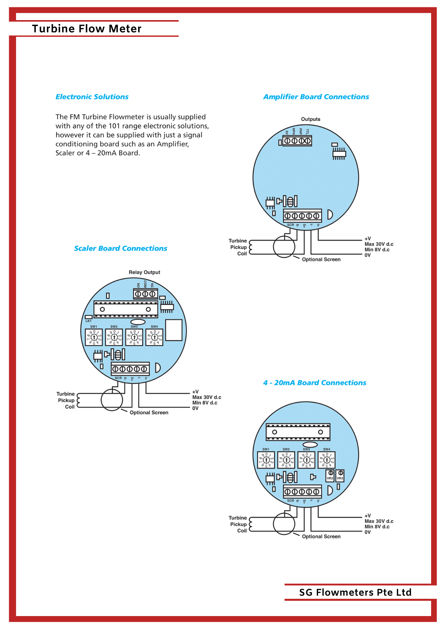
Output: is a low level signal that ranges from 10 mV to 1 V peak to peak.
A screened twin core signal cable should be used for connection to the Pick Up.