
DESCRIPTION
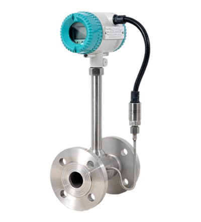
The KMETER Vortex flow meters utilize two primary sensing elements a vortex shedding velocity sensor and a RTD temperature sensor to measure the mass flow rate of gases, liquids and steam. Systems that use external process measurements to calculate mass flow may not provide adequate compensation for the fact that process conditions can change radically between the point of velocity measurement and the point where upstream or downstream pressure and temperature measurements are being made.
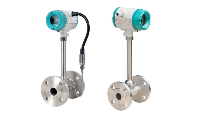
The KMETER multivariable flowrneter measures all of these parameters in a single location, it delivers a more accurate process measurement. Integrating muttivariable output capability with a single line penetration also simplifies system complexity and helps reduce initial equipment cost, installation cost and maintenance costs. The product line is available with a wide range of options and meter configurations to meet your specific application requirements.
Volumetric or mass flow monitoring of gases, liquids and steam Ideal for steam applications.
Selectable outputs for five process parameters in one integrated meter:
- Mass flow rate
- Volumetric flow rate
- Temperature
- Pressure
- Density
What is Vortex Flow Meter?
A Vortex flow meter measures flows of liquids, gases and steam by sending the frequency at which vortices are alternately shed from a bluff body. The frequency at which the vortices are alternately shed is directly proportional to the flow velocity.
Flow measurement based on the vortex principle: Here is an explanation of how this flow measurement method works. Inside each vortex flow meter, a bluff body is located in the middle of the pipe. This body is a kind of obstruction that disturbs the flow.
Downstream of the bluff body is a mechanical sensor which can measure the tiniest pressure differences in the flowing fluid. If the fluid is not flowing, no vortices form. As soon as the fluid starts to move and reaches a certain flow rate, vortices gradually appear downstream of the bluff body.
The vortices are present either side of the bluff body and are carried away by the flowing fluid. Zones of high or low pressure now appear downstream and thus create a phenomenon that is known as the Karman vortex street. These differences in pressure exactly match the frequency of the passing vortices and are precisely registered by the mechanical sensor shown in the video in slow motion.
This sensor is unique because it is so well balanced that high amounts of pipe borne vibrations, pressure surges and temperature shocks have no effect whatsoever on the measurement. The distance between two consecutive vortices corresponds to a defined volume of fluid. Therefore, total flow can be calculated by counting the vortices that pass. The higher the flow velocity, the higher the measured frequency of vortices. In some applications, the velocity is too low for perceptible vortices to form. However, the velocity can be increased simply installing a vortex meter that has a reduced cross section and this modification does not affect the measuring accuracy. Functionality can be enhanced by incorporating optional temperature measurement into the sensor. A configuration as such, together with a built-in flow computer can calculate temperature dependant mass or energy flow important in certain industrial processes involving saturated steam or gases.
For Australian players interested in maximizing their winnings, understanding the payout rates of online casinos is crucial. The article at https://arabpaths.com/top-payout-online-casinos-australia-overview/ offers a detailed analysis of the top payout online casinos available, helping players make informed decisions.